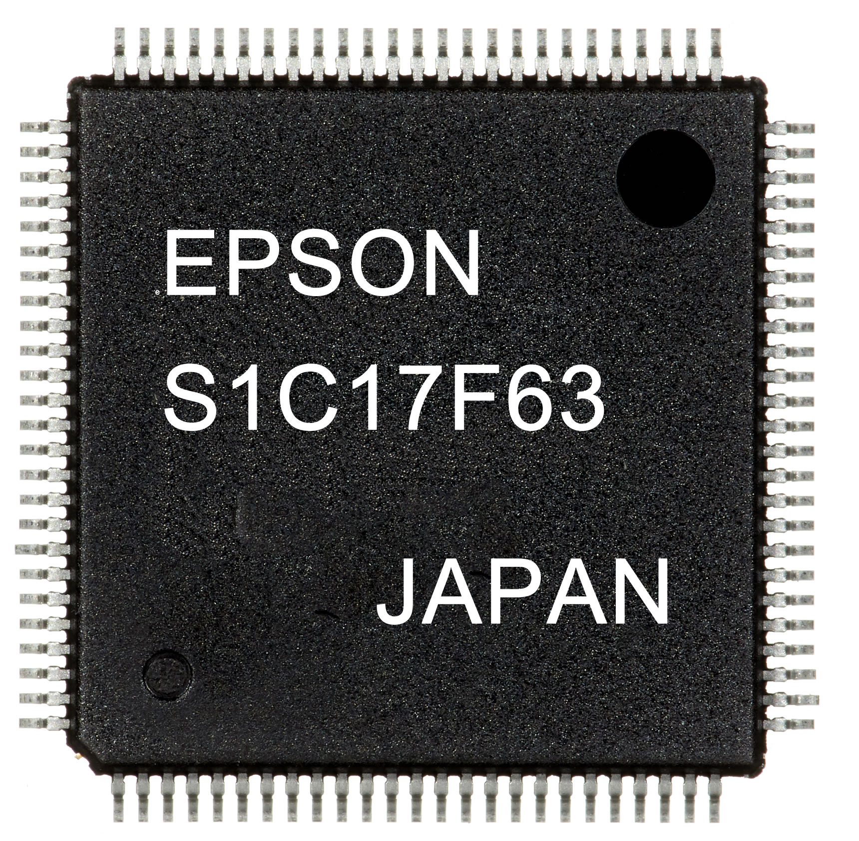
Epson Develops New 16-Bit Microcontroller with e-Paper Driver
S1C17F63 microcontroller ideal for smart cards with displays and other applications using small e-paper screens
Munich, November 20, 2019 – Seiko Epson Corporation (TSE: 6724,”Epson”) has developed and begun shipping samples of the S1C17F63, a 16-bit microcontroller unit (MCU) with a built-in driver that is ideal for driving small e-paper displays. Epson plans to produce 500,000 of these MCUs per month. 
The market for e-paper displays is expanding. These displays are flexible, offer paper-like legibility, and consume very little power, since no power is needed to keep data on the screen. They are being used in place of liquid crystal displays for everything from e-books and signage to electronic shelf labels and particularly smart cards. In smart cards, one-time password cards and dynamic CVV/CVC*1 cards with security codes that change at regular intervals are seen as a means to provide stronger protection against phishing attacks, which are causing mounting losses as online banking and payments become increasingly common. However, there are problems that need to be addressed with current embedded-display cards, which are susceptible to electronic component damage if bent or subjected to other physical stresses and which have limited battery capacity due to the limitations of the card configuration.
To solve these problems, Epson developed a single-chip microcontroller with built-in driver circuitry engineered specifically for e-paper displays. Since there is no need for external drivers, having built-in drivers reduces the component count, shrinks chip size through optimization of built-in peripheral circuits, and increases card durability. Epson also successfully reduced current consumption in real-time clock operation mode to 120 nA (typ.), a 40% reduction compared to a comparable earlier MCU.*2 The low power draw makes it possible to extend the battery life of the product without increasing battery capacity. Moreover, the extra current can be used to rewrite a display screen, making it possible to shorten the interval between security code updates, thus contributing to enhanced protection.
In addition to the display driver circuit, the new MCU offers Flash memory, EEPROM, timers, an A/D converter, and a temperature sensor. The built-in temperature sensor can be used to compensate display quality effects arising from the temperature characteristics of e-paper displays. The sensor can also be used together with a theoretical regulation function*3 to compensate for temperature-induced frequency drift in crystals. Updating passwords requires synchronization between a card terminal and system server, so accurate time measurements that are not affected by the ambient environment increase the security system value of customers.
Epson is committed to helping its customers improve the performance of their products with solutions that leverage Epson’s efficient, compact, and precision technologies.
*1 Codes designed to prevent credit card and debit card fraud. CVC: Card Verification Code (Mastercard) CVV: Card Verification Value (Visa)
*2 Epson’s S1C17F57
*3 A function that compensates crystal frequency deviation without changing external components
Notes: See the website below for more information about this product.
Product features
- Driver circuit optimized for e-paper displays
- 42-segment output
- Selectable segment, back plane, and top plane output pin assignments
- Display drive power supply control function
- Built-in display driving waveform generator
- Built-in display data memory
- Built-in temperature sensor
- Low-current real-time clock circuit that extends battery life
- 32.768 kHz (typ.) crystal oscillation circuit
- Operating current 120 nA (typ)
- Real-time clock (second, minute, hour, day, day of the week, month, and year counters)
- Day/hour/minute/second, alarm, and programmable periodic timer interrupts
- A theoretical regulation function that can be used to compensate temperature-induced drift of the oscillation frequency
| Product number |
S1C17F63 |
| CPU core |
16-bit RISC processor |
| Flash memory |
32 Kbytes |
| EEPROM |
256 bytes |
| RAM |
2 Kbytes |
| EPD controller/driver |
Segment output: 42
Top plane output: 1
Back plane output: 1
Output voltage 48 values
Built-in display drive power supply circuit |
| Real-time clock |
Second, minute, hour, day, day of the week, month, and year counters
Automatic leap year compensation
Day/hour/minute/second, alarm, and programmable periodic timer interrupts |
| Serial interfaces |
SPI |
2 channel |
| I²C |
1 channel |
| UART |
1 channel |
| Smart card interface |
1 channel |
| A/D converter |
12-bit successive-approximation ADC
External signal inputs: 7 max.
Internal signal inputs: 1 Connect temperature sensor output |
Temperature sensor / reference
voltage generator circuit |
Sensor output can be read by the A/D converter
The A/D converter reference voltage is selectable (2.0 V, 2.5 V, VDD or external source) |
| Supply voltage detector |
32 levels (1.2 V to 5.0 V) |
| Timer |
16-bit timer: 4 channels 16-bit PWM timer: 2 channels
Watchdog timer |
| I/O ports |
Max. 17 bits
Universal port multiplexer: 14 bits |
| Operating voltage |
1.8 V to 5.5 V |
| Current consumption |
Real-time clock mode: 120 nA (typical)
RUN: 5 µA@32 kHz (typ.)
RUN: 120 µA/MHz (typ.) |
| Package |
Gold bump chip [bump pitch: 85 µm (min.)]
Aluminum pad chip [pad pitch: 85 µm (min.)]
QFP15-100 (pin pitch: 0.5 mm) |
